1. Introduction
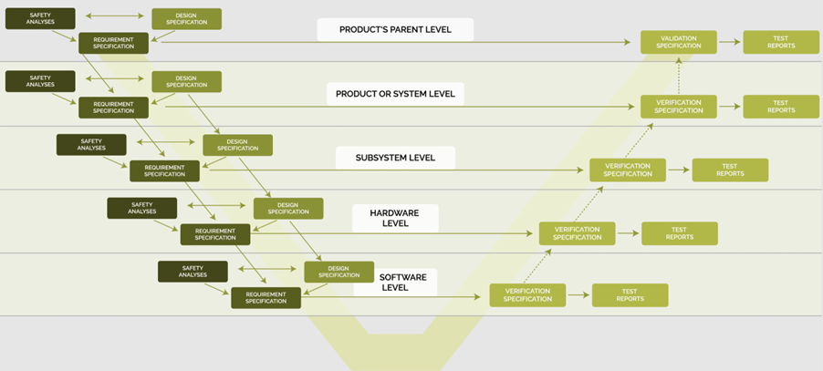
Functional safety standards require the development of a safety-critical product to be done according to the V-model of system development. Fig. 1 shows this V-model in the form that underlies the autoConform® methodology and software.

Fig. 1: System development V-model of the autoConform® methodology and software
In the V-model of Fig. 1, a single box usually does not stand for one work product, but for several work products. Section 2 elaborates on these work products. Section 3 explains why it makes sense to create all of these work products and how it can be done in a time-saving way.
2. Work Products on the Left Side of the V-Model
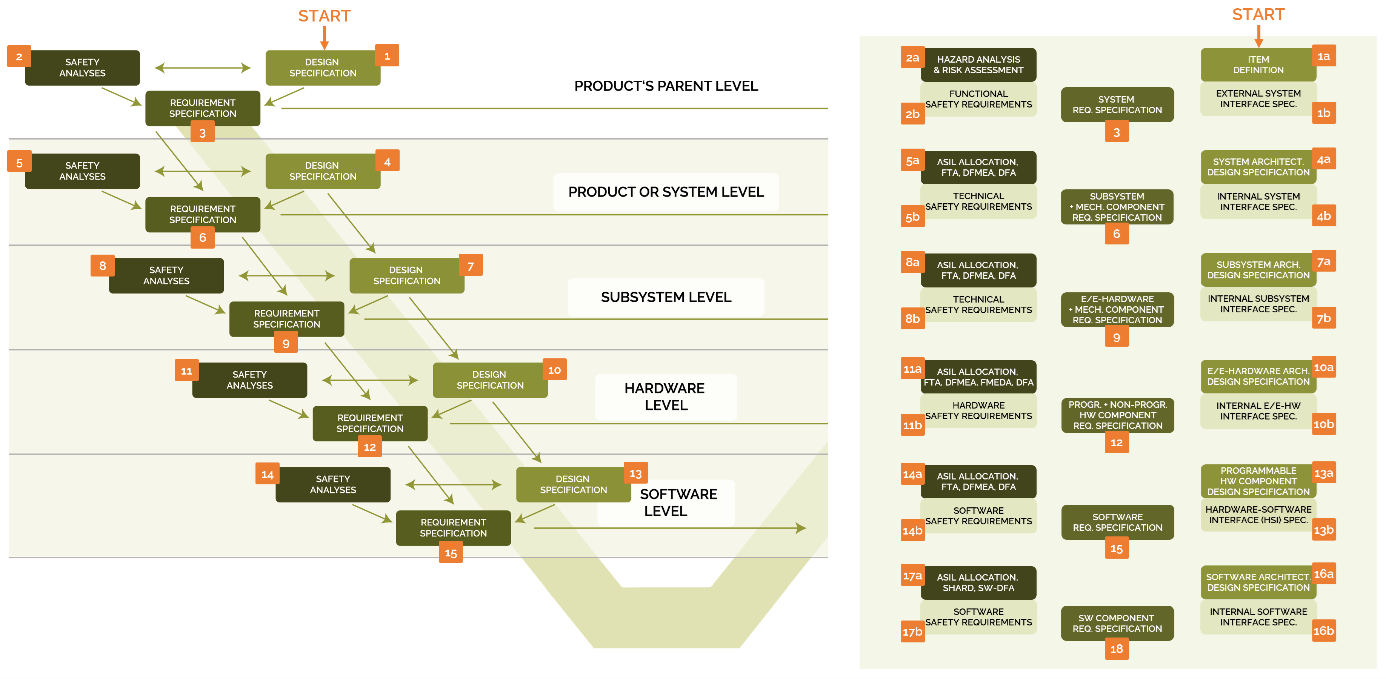
Fig. 2 shows how the left side of the V-model of Fig. 1 is „translated“ into specific work products.
Fig. 2: Translation of the left side of the V-model into specific work products
The starting point of the V-model is the design specification (1) at the top level, the „Product's Parent Level". This design specification is subdivided into two documents:
1a) the specification document "Item Definition", which describes the environment, interfaces, functions and static properties of the product to be developed, and
1b) the interface document "External System Interface Specification", which specifies all intended and unintended interactions of the product with its environment and with other external systems in the form of mechanical, electrical, communication, etc. intended signals, as well as unintentional but unavoidable disturbance signals.
The safety analyses (2) at the top level correspond to the Hazard Analysis and Risk Assessment (HARA, 2a) of the product and the safety requirements derived from it (2b). The main results of the HARA (2a) are
- the safety goals of the product to be developed, and
- the Safety Integrity Level (SIL) of each safety goal and thus also of each product output.
The highest safety integrity level assigned to one or more of the product outputs in the HARA equals the safety integrity level of the entire product. All safety integrity levels determined by the HARA are entered in the previously created work products "Item Definition" (1a) and "External System Interface Specification" (1b).
The product safety requirements, which are derived from the HARA in conjunction with the "Item Definition" and the "External System Interface Specification", form the Functional Safety Concept (FSC, 2b) of the product.
The FSC, if included in the system requirements (3), usually only represents a small part of (3). The majority of the system requirements (3) are derived directly from the "Item Definition" (1a), the "External System Interface Specification" (1b) and higher-level product requirements.
At the next level, the product or system level, the first thing to do is to create the design specification (4). This design specification (4) is subdivided into
4a) the specification document "System Architectural Design Specification", which specifies
- the system,
- the system states and modes of operation, and
- the system elements with their
- Interfaces
- Functions
- system state-dependent function activations and
- static properties.
and
4b) the interface document "Internal System Interface Specification", which specifies all intended and unintended interactions between the system elements inside the system or product.
The safety analyses (5) include
5a) the following analyses of the product architecture and design:
- SIL allocation (in automotive engineering: ASIL allocation),
- Fault Tree Analysis (FTA),
- Design Failure Mode and Effects Analysis (DFMEA) and
- Dependent Failure Analysis (DFA),
and
5b) Requirements for the system elements resulting from the safety analyses “SIL allocation”, “DFMEA” and “DFA” in (5a).
The SIL allocation in (5a) determines the safety integrity level of the outputs and inputs of each system element, and thus also the safety integrity level of each individual system element. Analogous to the level above, the safety integrity levels determined by the SIL allocation are entered into the previously created work products "System Architectural Design Specification" (4a) and "Internal System Interface Specification" (4b) at the system level. However, we still recommend to create the document "SIL Allocation at System Level" as a standalone work product and include it in the bi-directionally traced work product list which forms the basis for the safety case.
The purpose of the FTA in (5a) is to determine the single-point and multiple-point faults that can lead to the violation of a safety goal. The single-point faults identified in the FTA (specifically by the analysis part "Cut Set Analysis") are subsequently dealt with in a DFMEA. In such a DFMEA, the needed single-point fault prevention and mitigation measures are defined, and the associated requirements are formulated. Analogous to the treatment of single-point faults in a DFMEA, the multiple-point faults, especially the dual-point faults identified in the FTA are analyzed in a DFA, and technical safety requirements for the mitigation and prevention of multiple-point faults are formulated within the framework of the DFA.
The requirements (5b) are referred to as 'technical safety requirements'. They are typically included in the technical requirements (6) for the system elements, but usually form only a fraction of the requirements (6). The majority of the requirements (6) are derived directly from the work products (4a) and (4b) as well as the higher-level requirements (3).
At the product architecture levels below the system level, the structure of the work products just described for the system level is repeated. At the electric/electronic (E/E) hardware level, an FMEDA ("Failure Modes, Effects and Diagnostic Analysis") has to be added to the safety analyses. The FMEDA provides quantitative estimates of the reliability of the E/E design.
When analyzing the software architecture and design,
- the deductive analysis method “FTA” and
- the inductive analysis method “DFMEA”
can be combined to a single analysis method, the SHARD ("Software Hazard Analysis and Resolution in Design").
Matching Fig. 1 and Fig. 2, Table 1 lists each individual work product on the left side of the V-model.
Table 1: List of essential work products on the left side of the V-model
| Current No. | Title of the work product | No. in Fig. 2 |
| 1 | Item Definition | 1a |
| 2 | External System Interface Specification | 1b |
| 3 | Hazard Analysis and Risk Assessment (HARA) | 2a |
| 4 | Functional Safety Concept | 2b |
| 5 | System Requirements Specification | 3 |
| 6 | System Architectural Design Specification | 4a |
| 7 | Internal System Interface Specification | 4b |
| 8 | SIL Allocation at System Level | 5a, 5b |
| 9 | Fault Tree Analysis at System Level | 5a |
| 10 | Design FMEA at System Level | 5a, 5b |
| 11 | Dependent Failure Analysis at System Level | 5a, 5b |
| 12 | Subsystem Requirement Specifications | 6 |
| 13 | Subsystem Architectural Design Specification | 7a |
| 14 | Internal Subsystem Interface Specification | 7b |
| 15 | SIL Allocation at Subsystem Level | 8a, 8b |
| 16 | Fault Tree Analysis at Subsystem Level | 8a |
| 17 | Design FMEA at subsystem level | 8a, 8b |
| 18 | Dependent Failure Analysis at Subsystem Level | 8a, 8b |
| 19 | Hardware Requirements Specifications | 9 |
| 20 | Hardware Architectural Design Specification | 10a |
| 21 | Internal Hardware Interface Specification | 10b |
| 22 | SIL Allocation at Hardware Level | 11a, 11b |
| 23 | Fault Tree Analysis at Hardware Level | 11a |
| 24 | Design FMEA at Hardware Level | 11a, 11b |
| 25 | Dependent Failure Analysis at Hardware Level | 11a, 11b |
| 26 | Requirement Specifications for Programmable and Non-Programmable Hardware Components | 12 |
| 27 | Programmable Hardware Component Design Specification | 13a |
| 28 | Hardware-Software Interface (HSI) Specification | 13b |
| 29 | SIL Allocation at Software Level | 14a, 14b |
| 30 | Fault Tree Analysis at Software Level | 14a |
| 31 | Design FMEA at Software Level | 14a, 14b |
| 32 | Dependent Failure Analysis at Software Level | 14a, 14b |
| 33 | Software Requirements Specification | 15 |
| 34 | Software Architectural Design Specifications | 16a |
| 35 | Internal Software Interface Specifications | 16b |
| 36 | SIL Allocation at Software Detailed Design Level | 17a, 17b |
| 37 | SHARD at Software Detailed Design Level | 17a, 17b |
| 38 | DFA at Software Detailed Design Level | 17a, 17b |
| 39 | Software Component Requirement Specifications | 18 |
3. Work Product Creation
The total number of work products depends on the number of product architecture levels. Table 1 lists the work products for a product with the architecture levels
- system level,
- subsystem level,
- E/E hardware level,
- (entire) software level and
- software detailed design level.
If the product consists of just a printed circuit board in a housing, then both the system level and the subsystem level (and the work products associated with these two levels) do not exist. On the other hand, it is possible for a product to have a subsubsystem level in addition to the system and subsystem levels. The software architecture can also be subdivided into more than one software detailed design level. The conclusion from these observation is that unnecessary analysis and documentation effort can be avoided by defining the absolutely necessary product architecture levels only.
In view of the high number of work products in Table 1, the obvious question is whether the number of work products can be reduced. With a given product architecture and a given number of product architecture levels, it is unfortunately not possible to simply omit individual work products, because otherwise either
- the full traceability of technical requirements and design decisions would would be lost, or
- some of the safety analyses, which are required by functional safety standards, may not be done.
Fortunately, the autoConform® software is a tool that provides suitable templates for all work products and fills large parts of them automatically. With the autoConform® software, it is possible to create all work products in a complete, consistent, correctly and, not least to mention, in a very time-saving manner.


