Logo automated conformance GmbH

HOW WE WORK

We help companies across various industries to develop systems – at concept, system, hardware and software level. We strive to ensure that every system development project we are involved in is done right – right from the start.

Developing a system requires a multi-disciplinary collaboration of

various engineering disciplines,

marketing and sales,

commercial and legal specialists,

suppliers,

customers

and others.

Fig. 1: System development is team work.

The technical system development starts with the System Definition, which summarizes key system design decisions that need to be known from the very beginning.

Fig. 2: The System Definition

The System Definition contains:

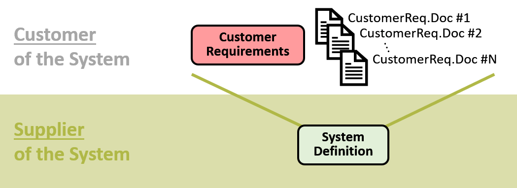
a general description of the system to be developed,

a description of the larger system into which the system to be developed will be integrated,

a description of all external elements (in the larger system) which will interact with the system to be developed,

a specification of the system functions,

a specification of all functional inputs and outputs of the system,

a description of the environmental influences and emissions of the system.

Once the System Definition (or a preliminary version thereof) is available, the subsequent technical system development is accomplished through Model-Based Systems Engineering (MBSE). Here we mean by MBSE that the entire technical system development process is based upon and is accompanied by the development of an executable block-oriented system and system context model. Subsequently, this model will simply be referred to as the System Model

At every stage of the technical system development process, the System Model represents, with sufficient accuracy,  the system’s functionality and behaviour as developed and known at that point in time. At the very beginning of the technical system develepment process, the System Model is a first conceptual model of the system; at the end it is a full representation of the system’s dynamic behaviour.

Note that the System Model not only represents the system’s intended functionality. The model also includes 

  • unintended influences (which are non-functional inputs) and
  • unintended effects (which are non-functional outputs)

and thereby reflects non-functional requirements and test cases in addition to functional ones.

In our MBSE workflow, the System Model is not an object-oriented model, but a block-oriented Simulink® ¹ model. In a block-oriented system model, all relevant intended and unintended interactions

  • between the system and its environment as well as 
  • between all internal elements of the system

are modelled explicitly, making such a model suited for inductive and deductive system failure analyses as well as simulative fault injection tests. These analyses and simulative tests help to investigate potential quality and safety issues of the current system design. 

In the course of technical system development, many documents such as

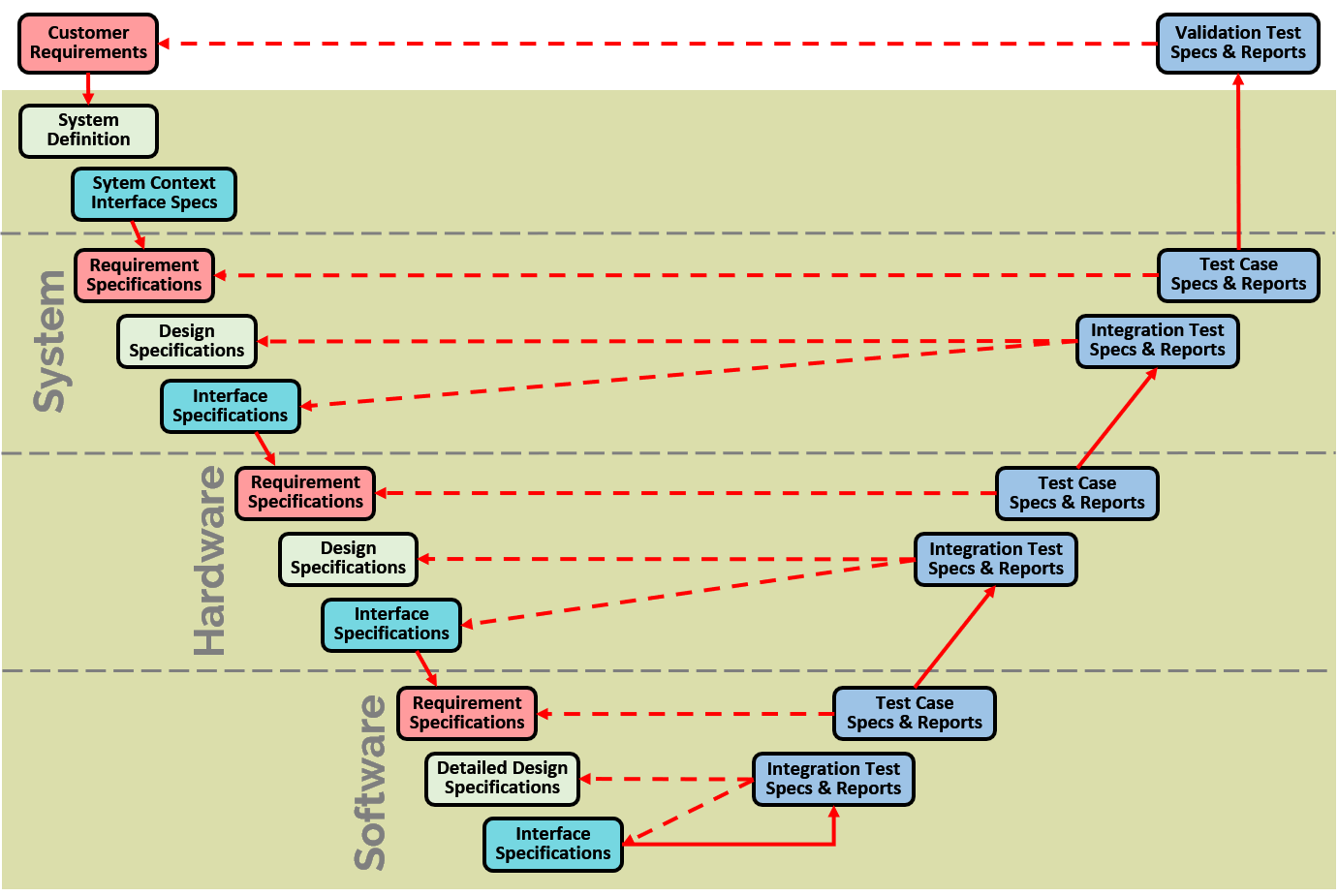
requirement specifications,

design specifications,

interface specifications as well as

test specifications and reports

have to be produced at system, hardware and software level , see Fig. 3.

Fig. 3: Selected documents that need to be created during system development

These documents are used as communication means between the various disciplines involved in developing the system. During the course and especially towards the end of a system development project, these documents are also used to prove that the system has been developed according to applicable legislation and standards. For the latter purpose, the documents have to be

complete,

consistent and

correct.

Our proprietary autoConform® Software Suite not only allows to speed up many workflow steps in MBSE. Primarily, the software makes it easier and faster for the systems engineers to produce system development documents (as shown in Fig. 3) which are complete, consistent and correct. In addition, the software highly automates inductive and deductive system model analyses as well as simulative tests. 

The autoConform® Software Suite comprises several software modules which are shown in Fig. 4. The figure also indicates that the autoConform® Software Suite stores all information in its own autoConform Project Repository. The software supports one or several system models, depending on the number of system variants that need to be developed.

Fig. 4: Modules of the autoConform® Software Suite.

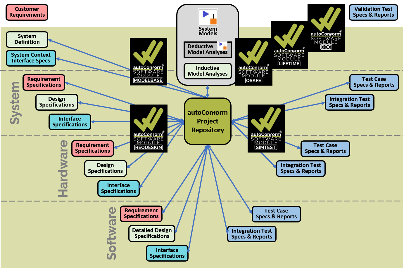
Note that all the artefacts in Fig. 4 (i.e., the documents, the System Models as well as the Deductive and Inductive Model Analyses) share a lot of information. However, every artefact contains some information that is not contained in any of the other artefacts. Therefore,

no artefact can be removed without losing information, and

each System Model (for each system variant) cannot be “the single source of truth” because it does not contain all information (about that system variant).

We not only develop and sell the autoConform® Software Suite. We also support customers directly in their system and software development projects by providing engineering work products which we create using the autoConform® Software Suite ourselves. In doing so, we achieve better results faster for our customers, and we also gain valuable insights as to how to improve our software.

¹ Simulink® is the registered trademark of The MathWorks®, Inc.